

 language




CNC machining · Grinding · Micro-hole machining
Keyto manufactures custom precision components. Our capabilities cover CNC machining, grinding, femtosecond laser machining and selected joining and molding processes across engineering plastics, metals, ceramics and other hard, brittle materials.
Use the component examples below to discuss your part geometry, material and inspection requirements. Share a drawing or specification to start a project review.
 Representative fluid distribution component
Component showcase
Representative component designs
Valve plates, fluid distribution parts, housings and precision components show the range of geometries available for discussion. These are reference designs for custom projects; dimensions, materials and manufacturing routes are defined for the individual part.
Valve plates & fluid distribution

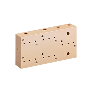
Multi-Port Valve Plate
A broad mounting face with multiple port and fixing-hole patterns.

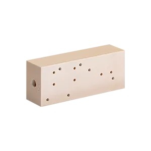
Valve Plate with Side Port
A rectangular plate with front-face holes and a side connection.

Channelled Valve Plate
A valve-plate design with visible channels and repeated port positions.

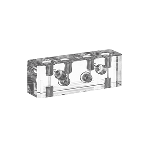
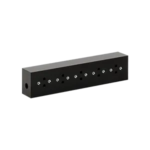
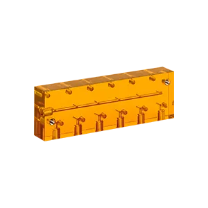
Elongated Valve Plate
An elongated block with a row of connection positions and an end port.
Housings, cylindrical parts & needles

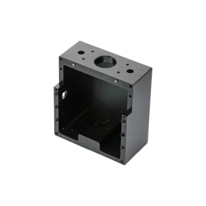
Machined Aluminum Housing
An open cavity with mounting features and bores on the top face.

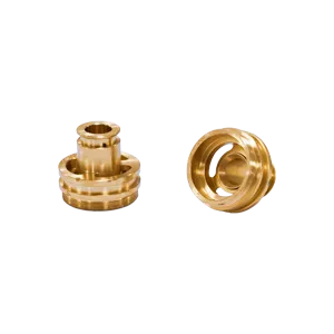
Stepped Brass Components
Stepped outer profiles and internal bores illustrate the component geometry.

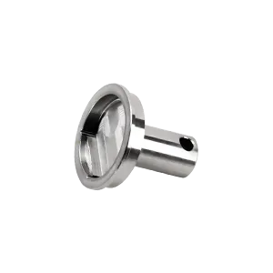
316L Stainless Steel Flanged Component
A circular flange, stepped opening and lateral hole in the stem.

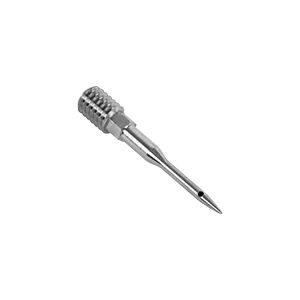
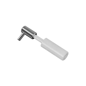
Titanium Alloy Needle
Brochure example: 0.6 mm hole diameter and 18 mm depth.
Ceramic & supporting components

Ceramic Metering Pump Component
Ceramic component for a metering pump, illustrated in the machining brochure.

Grooved Sapphire Component
A circular part with a recessed curved channel on its face.

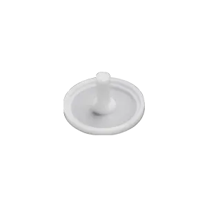
Diaphragm Component
A formed circular profile with a central stem and raised perimeter.
Manufacturing capabilities
Machining processes and production facilities
Part geometry, material and critical features guide the manufacturing route. Keyto combines CNC machining, grinding and laser micro-machining with additional joining and surface-treatment options where the part requires them.
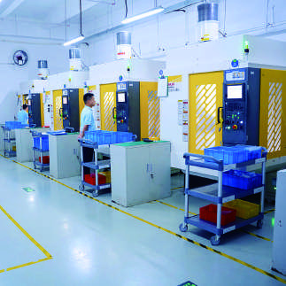
Machining workshop
Rows of machining centers and workpiece trays in Keyto's workshop.
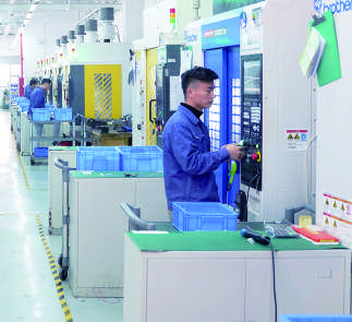
Machine operation
An operator at a machining center's control panel, with workpiece trays beside the workstation.
CNC machining & turning
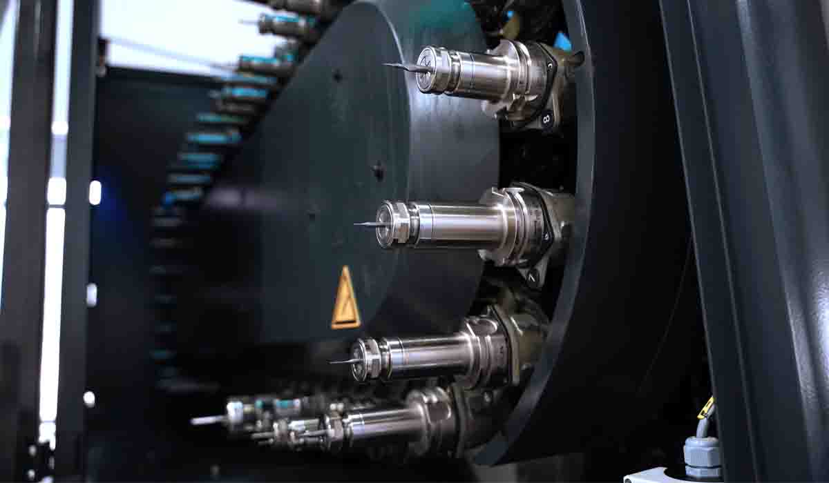
3-, 4- and 5-axis machining centers and CNC lathes support custom component geometries, machined ports, cavities and interfaces.
Grinding & precision features
Honing, centerless, cylindrical, coordinate and surface grinding are available for components requiring controlled geometry and surface finish.
Laser micro-hole machining
Femtosecond laser machining supports micro-holes and shaped features. See the film-aperture example below for a documented hole size and accuracy.
Additional process options include bonding, laser and ultrasonic welding, injection molding, plasma treatment and metallization. The material and geometry determine which process combination is suitable.
Material options
Engineering plastics, metals and hard materials
| Material family | Examples listed in the machining brochure |
|---|---|
| Engineering plastics | PMMA, PEI, PTFE, PCTFE, PEEK, PVDF, PET and PI |
| Metals | Titanium alloys, stainless steel, copper, aluminum and nickel |
| Hard and brittle materials | Ceramics, sapphire and borosilicate glass |
Specify the material grade, fluid or reagent exposure, operating temperature and any surface-treatment requirements when requesting a review.
Documented examples
Dimensions tied to specific components
The following examples illustrate different machining tasks. They are not a common specification for every component shown above.
| Component / feature | Material | Example dimensions or geometry |
|---|---|---|
| Micro connector | PMMA / PEI | Hole diameter: 0.07 mm Depth: 1.5 mm |
| Spray needle holder | PEEK | Hole diameter: 0.15 mm Concentricity: 0.02 mm |
| Metering-pump sleeve and rod | Zirconia / alumina options | Cylindricity: 0.0015 mm (sleeve) 0.001 mm (rod) |
| Needle | Titanium alloy | Hole diameter: 0.6 mm Depth: 18 mm |
| Long-core needle tube | POM | Hole diameter: 0.8 mm Length: 50.6 mm |
| Laser-machined aperture | Film | Minimum hole diameter: 7 μm Accuracy: ±1 μm |
Inspection capabilities
Measurement methods for critical part features
The inspection equipment below supports the evaluation of dimensional, geometric and surface features. Identify the features that matter for your part so the measurement method can be discussed alongside the manufacturing process.
| Feature to inspect | Inspection equipment |
|---|---|
| Cylindricity | Cylindricity measuring instrument |
| Surface roughness | White light interferometer |
| Flatness | White light interferometer |
| Micro-hole dimensions | OGP measuring system |
| Positional accuracy | Coordinate measuring machine (CMM) |
| Concentricity | Coordinate measuring machine (CMM) |
| Outer diameter | Laser diameter gauge |
| Inner diameter | Pneumatic gauge |
Agree on what needs to be measured
Mark critical dimensions, datums, surface requirements and acceptance criteria on your drawing. Inspection methods and reporting requirements are confirmed for the individual part during project review.
Start a project review
Send your drawing and critical requirements
For a useful first discussion, include:
- A 2D drawing, 3D model or dimensioned concept sketch
- Material grade and the part’s function or operating environment
- Critical dimensions, tolerances, surface finish and inspection requirements
- Prototype quantity, expected production volume and timing
If your drawings are confidential, ask about an NDA before sharing project details.
Related: Customizable parts · Manifolds & microfluidic chips