

 language

-
Home
-
Products and Solutions
-
Keyto Global
-
News Center
-
Service Support
-
About Us
-
Contact Us
-
Language

Air displacement pipette accuracy describes how closely a delivered volume agrees with its target. It depends on the liquid, tip, temperature, seal integrity and programmed pipetting sequence. For an OEM instrument, a water test is a useful reference, but application performance must be verified with the intended liquid and operating conditions.
A useful specification therefore answers two questions: How far is the mean delivered volume from the target, and how much do repeated deliveries vary? A low coefficient of variation (CV) answers the second question. It does not establish the first.
This guide connects the air displacement pipette mechanism to practical error diagnosis, automated method development and module selection.
View the verification checklist →
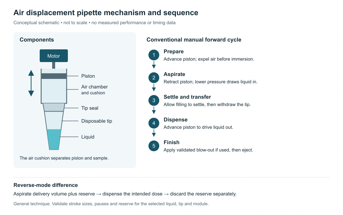
An air displacement pipette uses a moving piston to change pressure in an air cushion between the piston and the liquid. During aspiration, piston retraction expands the available air space and lowers its pressure. Pressure acting on the source liquid then drives liquid into the tip. The piston normally remains separated from the sample by air. Thermo Fisher Scientific explains this operating principle.
The core air displacement pipette parts are the piston, chamber and disposable tip. An automated module adds the drive and control functions needed to coordinate their operation.
| Component | Function | Relevance to delivered volume |
|---|---|---|
| Piston and cylinder | Change the enclosed air volume | Piston movement sets the mechanical displacement; sealing affects pressure transfer. |
| Air chamber and air cushion | Transmit pressure changes to the liquid | Air responds to pressure, temperature and evaporation. |
| Tip interface and seals | Connect the disposable tip to the air path | A poor seal can disrupt aspiration and liquid retention. |
| Disposable tip | Hold and release the sample | Fit, geometry, wetting and liquid retention influence transfer. |
| Motor, transmission and controller | Execute piston movement and timing | Supported speed settings, pauses and stroke sequence define the method; configurable parameters vary by module and firmware. |
| Z-axis and sensing, where fitted | Position the tip and detect process conditions | Immersion and withdrawal must remain coordinated with aspiration. |
In the conventional manual forward technique, the piston first advances while the tip is outside the liquid to prepare the aspiration stroke. After immersion, it retracts to aspirate. The method then allows liquid movement to settle before the tip leaves the source. At the destination, piston advance drives dispensing; a separate blow-out may follow if the validated method requires it.
The pressure reduction that draws liquid into the tip occurs during piston retraction. The preparatory downward movement expels air; describing that movement as creating the aspiration vacuum reverses the mechanism.
For automation, define the complete sequence from initialization and tip pickup to aspiration, transfer and dispensing. If the method includes air gaps, account for those volumes separately from the intended liquid dose. Check how the controller interprets each volume command, including any step used to empty the tip.
A delivered-volume result belongs to a defined combination of module, liquid, tip and method. Changing one of those conditions can change the result even when the commanded volume stays the same. Eppendorf identifies liquid viscosity, volatility and density, together with environmental conditions, as influences on air-cushion pipetting. Eppendorf technical overview.
Report systematic volume error and repeatability separately, using explicit units and definitions:
For example, a hypothetical 100 µL target with a 98 µL mean and a 0.49 µL SD gives −2.0% relative systematic error, 2.0% absolute relative deviation and 0.50% CV. Deliveries are closely grouped, but the mean is below target. This calculation illustrates the definitions; it is not a Keyto test result.
When comparing pipetting specifications, check how the manufacturer defines accuracy. Signed systematic error shows whether the mean delivered volume is above or below the target, while absolute relative deviation expresses the size of that error without its direction. CV describes variation between repeated deliveries. Evaluate these metrics separately, together with the stated liquid, volume, tip and test conditions. A result at one volume does not establish performance across the full operating range.
The following matrix is an engineering troubleshooting guide. Symptoms can have several causes; each suggested check is a starting point for a controlled investigation, not a confirmed diagnosis or universal parameter setting.
| Factor | Mechanism and possible symptom | Controlled check for an OEM instrument |
|---|---|---|
| Viscosity | Slow filling or draining can leave incomplete aspiration or retained liquid. | Compare aspiration speed and settling time separately; inspect residual liquid and evaluate a supported dispensing sequence. |
| Volatility | Evaporation into the air cushion can promote dripping and transfer loss. | Record liquid temperature and transfer delay; evaluate compatible preconditioning, air gaps and confirmed droplet-control functions. |
| Density | A different liquid-column load can shift delivery relative to a water adjustment. | Verify the actual liquid and use its appropriate density in gravimetric evaluation. |
| Surface tension and wetting | Wall films, attached droplets or foam can alter delivery. | Compare compatible tip surfaces and dispensing positions under the same method. |
| Temperature | Differences between liquid, tip and module can change the air cushion during a transfer. | Compare startup and steady operation; record actual liquid and instrument temperatures. |
| Tip fit and seals | Air leakage can cause underdelivery, dripping or inconsistent pickup results. | Inspect seals and seating; compare tip lots using an approved leak-check procedure. |
| Immersion and liquid level | Too little immersion can admit air; changing source level changes aspiration conditions. | Verify Z-position and level following at both high and low source fill levels. |
| Motion and timing | Early withdrawal or an unsuitable dispense sequence can interrupt transfer. | Change one setting at a time and retain the complete method revision with the results. |
| Calibration and measurement | Incorrect adjustment, evaporation during weighing or an unsuitable measurement method can distort conclusions. | Check the reference procedure and measurement uncertainty before changing calibration. |
The liquid-related mechanisms above are described in Thermo Fisher's technical note on liquid properties and pipetting. Tip preconditioning and controlled immersion are also addressed in Gilson's pipetting guidelines.
Use the matrix to build a test sequence. If water meets the acceptance criteria but the process liquid does not, investigate the liquid-specific method and measurement procedure first. If both fail, inspect the shared tip interface, mechanics and reference test conditions. These comparisons narrow the investigation without assuming that every error requires recalibration.
For temperature-sensitive workflows, test the required process temperature. Warming every sample to room temperature may be incompatible with the application.
Forward and reverse pipetting use different volume sequences. Forward mode is a common starting point for aqueous solutions. Reverse mode aspirates an additional volume and leaves a reserve after the intended dispense. It can help with some viscous or foaming liquids, but the transferred volume must be verified for that method. Thermo Fisher's pipetting mode definitions.
| Control step | Forward pipetting | Reverse pipetting |
|---|---|---|
| Prepare | Establish the starting piston position for the metered aspiration. | Establish a sequence that includes the selected reserve volume. |
| Aspirate | Draw the method's programmed volume. | Draw the programmed delivery volume plus reserve. |
| Settle and transfer | Apply the validated pause and withdrawal sequence. | Apply the validated pause and withdrawal sequence; account for the larger aspirated volume. |
| Dispense | Deliver the intended dose and apply blow-out if specified. | Deliver the intended dose while retaining the reserve. |
| Finish | Clear or eject the tip according to the method. | Discard the reserve separately according to the method. Do not add it to the intended dose. |
For automation, translate each technique into a sequence supported by the selected module and controller. Define the aspiration volume, delivered dose, retained reserve and final emptying step explicitly. Validate the sequence with the intended liquid and tip; manual “first stop” and “second stop” positions do not define a universal motor stroke or software command.
Post-dispense re-aspiration and reverse pipetting serve different purposes. A re-aspiration step draws back after dispensing to help control a hanging droplet. Reverse pipetting starts by aspirating an additional liquid reserve. When configuring a method, distinguish the two actions and verify their effect on the delivered dose.
The reserve consumes tip capacity and reagent volume. Include it when checking capacity, liquid clearance and waste handling. Record the applicable air gaps, mixing, speeds, pauses and any permitted tip preconditioning in the liquid class: the saved parameters for a defined liquid, tip and volume range. Follow the model's tip-use instructions; a preconditioning step is not permission to reuse a disposable tip across samples.
No. Reverse pipetting can reduce variation while shifting the mean delivered volume. Thermo Fisher's good laboratory pipetting guide describes possible overdelivery in reverse mode and recommends evaluating its effect. Compare both systematic error and CV before selecting the method. Thermo Scientific Good Laboratory Pipetting Guide.
For an OEM evaluation, hold the liquid, tip and temperature constant when comparing modes. After choosing a candidate method, verify it at the intended cycle time and across relevant source fill levels. A result obtained with long development pauses does not establish performance at production throughput.
Select a module against the application acceptance criteria and the conditions under which it will run. Begin with required volumes and allowable systematic error, then assess tip compatibility, repeatability, liquid handling controls, mechanical fit and communication requirements.
For single-channel configurations, review Keyto's air displacement pipetting modules. The SP13 air displacement pipetting module is one candidate to evaluate where its configuration fits the instrument. Confirm the selected hardware, supported functions and test conditions before treating a published specification as an application requirement.
If a liquid remains difficult after method development, evaluate whether direct piston contact with the liquid offers a better route. Positive displacement removes the intervening air cushion, but the chosen system still needs application testing. A short air vs positive displacement pipetting explanation can help frame that decision.
Ask what any process-monitoring feature actually measures. Liquid-level or pressure feedback can support fault detection; it does not by itself supply the measured volume data needed to establish systematic error and CV.
During module evaluation, confirm which droplet-control functions are available in the selected configuration and how they interact with aspiration and dispensing. Include the intended settings in the volume test. A method that prevents visible dripping must still meet the application’s systematic-error and repeatability limits.
A useful verification record links the results to the exact configuration and raw measurements. ISO 8655-6:2022 describes a gravimetric reference procedure for piston-operated volumetric apparatus, including the complete system and the selected parts involved in measurement. This supports evaluating the instrument and its consumables together. ISO 8655-6:2022 scope.
For an automated workflow, establish the applicable procedure with the responsible metrology or quality team. Merely weighing dispenses does not demonstrate compliance with the complete standard. Process-liquid testing also needs a suitable measurement method, including density and evaporation treatment where relevant.
Read each result together with its test conditions. A reference test using water and non-contact dispensing answers a different question from a process test using a viscous reagent at the instrument's required cycle time. Check that the evidence covers the liquid, volume, tip and sequence relevant to your application.
For aliquot dispensing, identify which doses are included in the calculation. If the method intentionally discards initial or final aliquots, record their positions and destinations, and distinguish the complete dispensing sequence from the doses evaluated. Results for retained aliquots cannot establish performance for excluded doses.
A performance summary can help shortlist a module. To accept it for an application, use a verification record that includes the underlying measurements, sample size, calculations and acceptance criteria.
Before accepting a performance claim, confirm that the record includes:
Choose replicate counts and test conditions through the applicable procedure and application risk assessment. Distinguish repeated dispenses using one tip from tests across new tips, lots, days or modules; these answer different questions.
Scope: The diagram and numerical example illustrate pipetting principles. The troubleshooting matrix and checklist support method development; application performance must be established through measurements under defined conditions.
About the technical reviewer
Lewis Zhang · Product Manager, Keyto